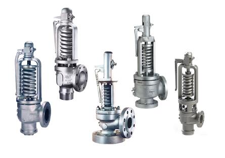
The working principle of spring safety valve
When the steam pressure under the relief valve disc exceeds the press pressure of the spring, the valve disc is pushed open. After opening the disc, the repulsive force of the lower adjustment ring causes the exhaust to act on the disc clamping ring, thus making the valve quickly open. As the disc moves upward, the steam tends to collide with the top regulation ring, while the exhaust steam tends to point vertically downward. The reaction force generated by the exhaust gas pushes the disc upward, thus keeping the disc within a certain pressure range. When the safety valve is opened with sufficient lift, steam is discharged continuously and the steam pressure in the system is gradually reduced. At this point, the force of the spring overcomes the steam pressure acting on the disc and the reaction force expelling the steam, thus closing the relief valve.
Structural characteristics of spring safety valve
A spring - loaded safety valve consists of a seat forming a disc and a sealing surface. The disc is connected to the stem. From closed to fully opened, the total displacement of the stem needs to meet the requirements of the valve. The setting pressure of the safety valve is mainly adjusted by adjusting the bolt to change the spring pressure. The valve is topped with a lever mechanism that is used to manually lift the stem during the run test. Valve body with upper and lower adjustment rings. The valve can be completely removed by adjusting the adjustment ring at the bottom. The top adjusting ring is used to adjust the return oil pressure. If the reinstall pressure is too low, the valve will remain open for an extended period of time. If the reinstallation pressure is too high, the valve will pulsate and remain closed, causing flutter, damaging the valve and reducing valve discharge. The top adjustment ring is positioned to allow the valve to reach max stroke.

Spring safety valve installation and maintenance
1) All safety valves shall be installed vertically.
2) In order to avoid pressure, the outlet of the safety valve should not have any resistance.
3) The safety valve should be specially tested and its air tightness checked before installation.
4) The safety valve in use should be checked regularly.
The safety valve must meet the following requirements
1) For boilers with rated evaporation capacity greater than 0.5t/h, please install at least two safety valves. Install at least one safety valve for boilers rated at 0.5t/h or less. The valve. The safety valve shall be installed at the outlet of the detachable economizer and steam superheater.
2) The safety valve shall be installed vertically in the max position of the boiler and the manifold box. There shall be no outlet pipe or valve between the relief valve and the drum or manifold for the suction of steam.
3) Lever safety valve needs a device to prevent the weight from moving itself and a guide frame to prevent the lever from slipping. Spring relief valves also require a lift handle to prevent accidental twisting of the regulating screws.
4) For boilers with rated steam pressure below 3.82MPa, the diameter of the pipe of the safety valve should be more than 25mm. For boilers with rated steam pressure greater than 3.82MPa, the diameter of the safety valve pipe should be at least 20mm.
5) The cross-sectional area of the connecting pipe between the safety valve and the boiler shall not be less than the cross-sectional area of the inlet of the safety valve. If multiple relief valves are connected to short tubes directly connected to the drum, the cross-sectional area of the short tubes shall not be 1.25 times the exhaust area of all relief valves.
6) Safety valves should usually be equipped with exhaust pipes. The exhaust pipe needs to be connected directly to a safe place and have sufficient cross-sectional area to ensure smooth exhaust. Connect the drain pipe to a safe place at the bottom of the relief valve exhaust pipe. Valves cannot be installed on exhaust pipes and drainpipes.


